Building an Electrocardiogram
The electrocardiogram (ECG) is a medical test that measures the electrical activity of the heart. The ECG measures voltages over time and can detect irregularities in the timing and progression of the heart’s contractile process.
For this project, I built an ECG circuit and recorded the activity of my heart. You can see a recording of the output signal here, and read about the technical details of the project below. I’m happy to report that the ECG shows no abnormal behavior!
Background
The heart is a biological electromechanical system that beats due to the movement of electrically charged particles into and out of heart cells. The ECG is an assessment of this electrical activity that shows the magnitude and direction of current flow in the heart.
ECGs used in hospital settings measure and display 12 “leads,” or electrical signals measured between electrodes attached to the patient. The output signal above is only one of these 12 signals; it shows the electrical signal detected between electrodes on the left and right wrists, or “Lead I.”
Circuit Building Blocks
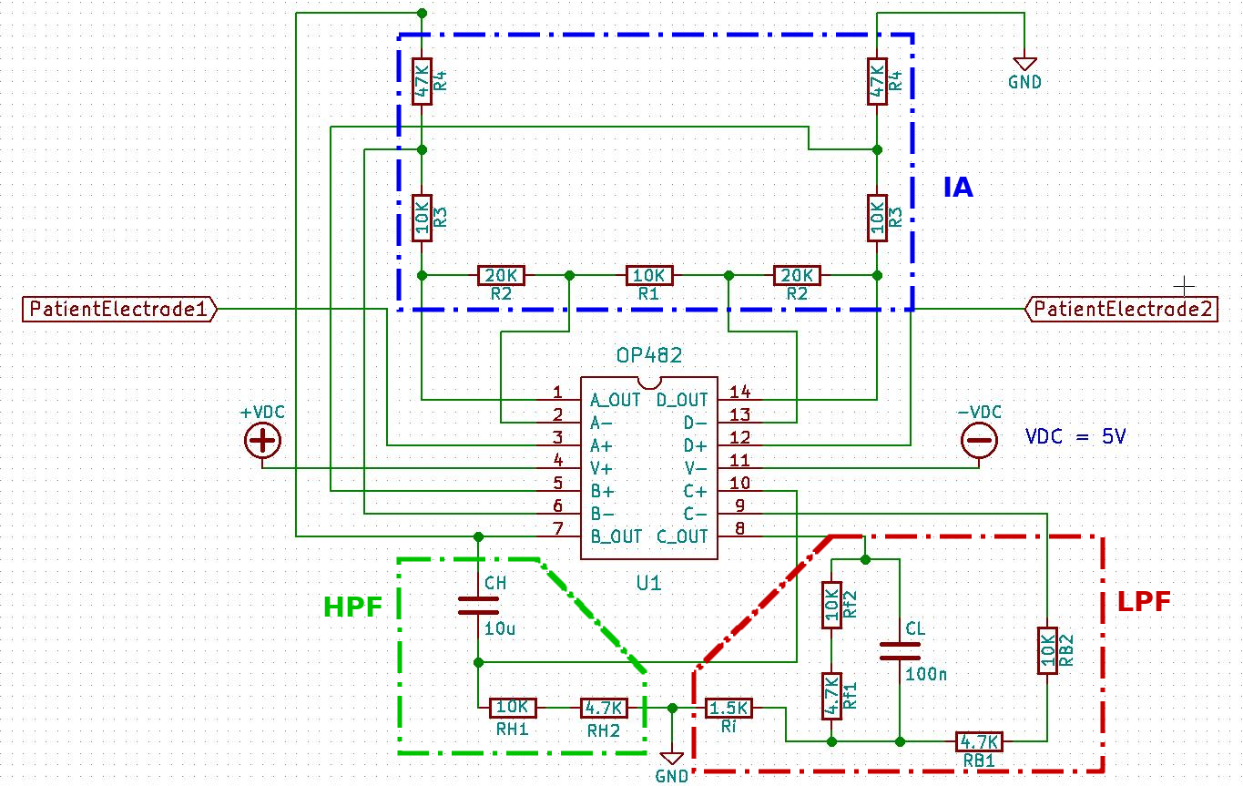
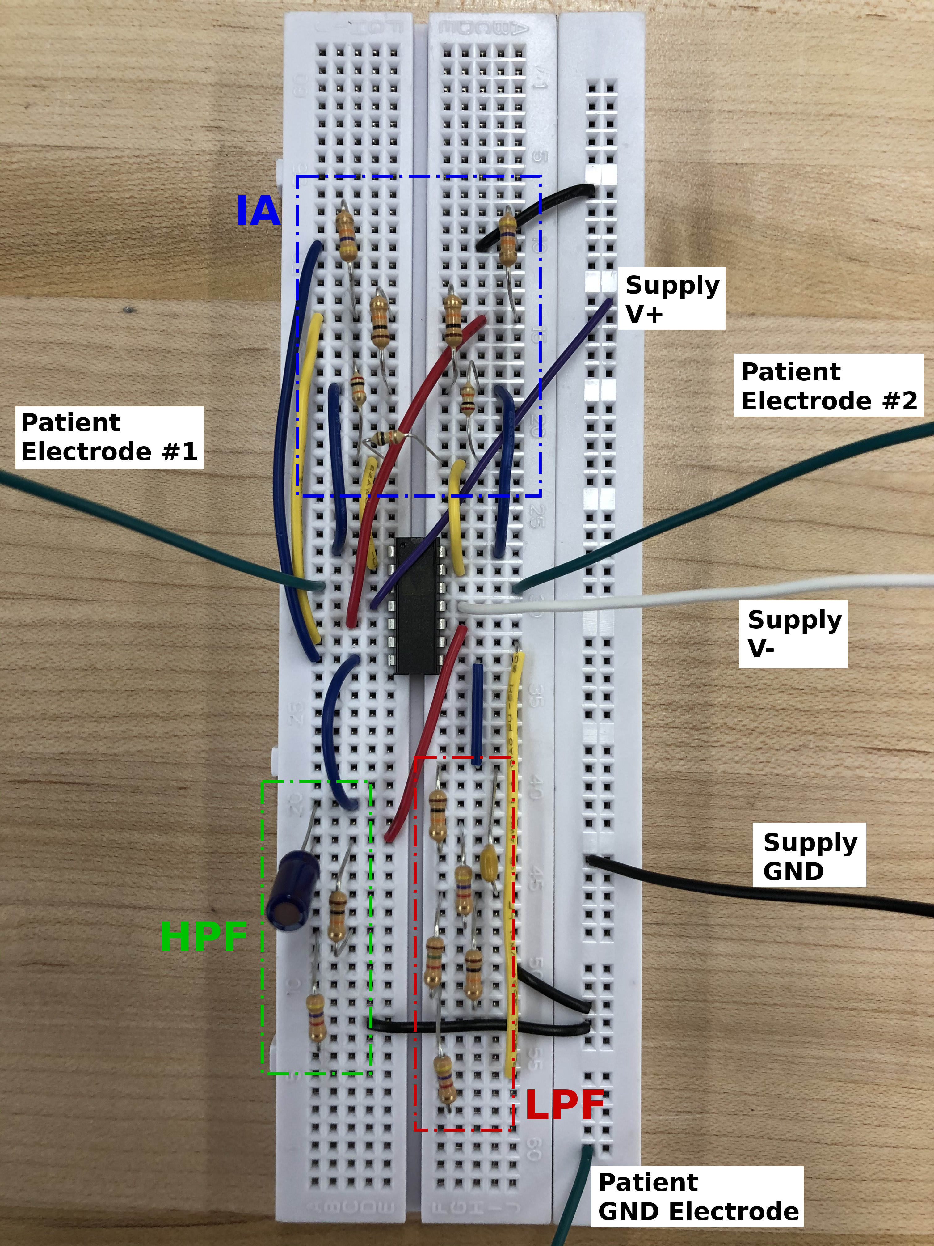
Bioelectric signals have very low magnitude and are also heavily influenced by noise. The ECG circuit I built for this project has three main components that each address one of these problems; I’ve briefly explained their functions below and have highlighted each component on the breadboard and circuit schematic images after.
- Instrumentation amplifier (IA): amplifies the signals obtained by the two electrodes, while simultaneously removing signal components that are the same at each electrode input.
- High-pass filter (HPF): prevents amplifier output saturation by eliminating DC components
- Low-pass filter (LPF): removes high-frequency noise from the LPF output